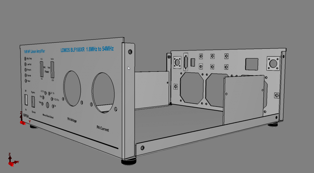
The general mechanical layout of the amplifier follows the W6PQL layout fairly closely.
The main difference is that the recommended heatsink he suggests is a bit expensive when you factor in shipping charges to the UK plus VAT & Customs etc. So I sourced a relatively inexpensive heatsink from the supplier TME in Poland which I think will have similar performance but is slightly longer, so makes the cabinet wider. This makes the whole box for the amplifier wider. For this reason I have the two meters for PA voltage and current side by side rather than one on top of each other as W6PQL does.
Mechanical Details
My metal working facilities are very limited, and my skill at it even more so. So rather than have separate panels bolted together I had a sheet metal box fabricated by an online vendor. A bit of a vanity project, as it looks nice and saves a lot of metal bashing, but is a cost. Another alternative could have been to mount the LPF alongside the heatsink and use a 19″ cabinet. That would be wider, but a lot shallower.`
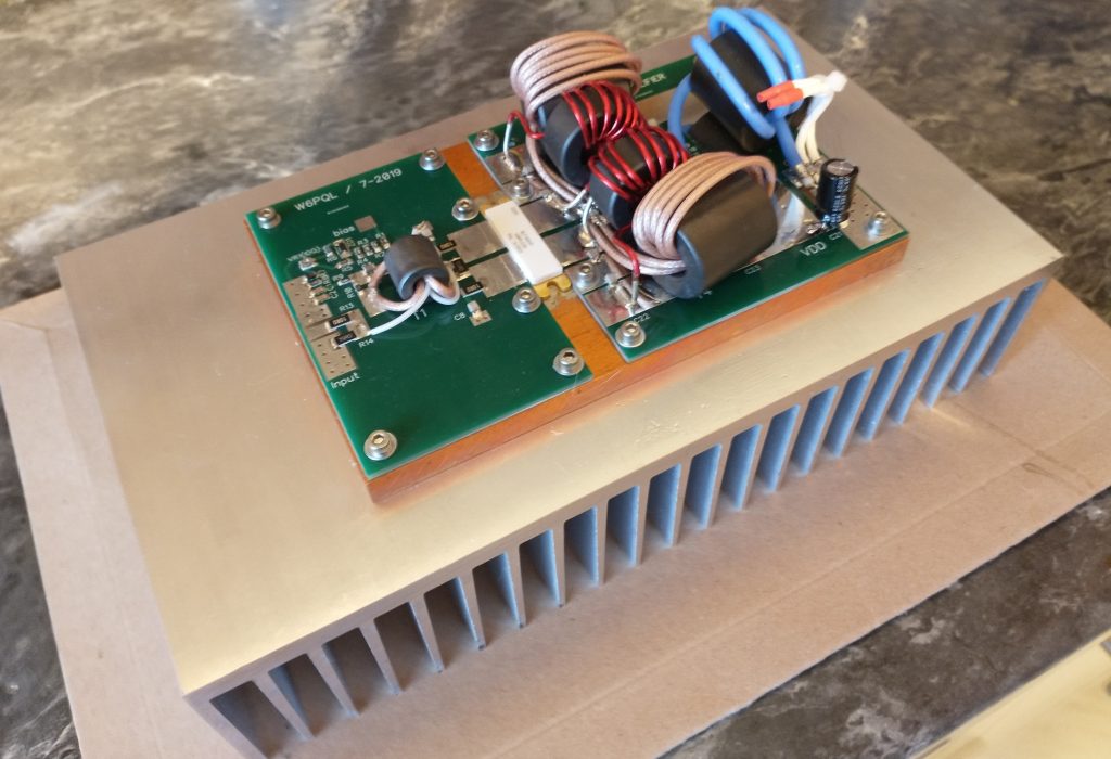
Three fans are mounted on the rear panel along with RF connectors, power, PTT . SMA RF connectors are used to bring out connections to a 13dB 100W attenuator that can be placed in circuit when 100W transceivers are used to drive the amplifier, or bypassed when 5W radios are used to drive the amplifier. The heatsink is mounted at the rear lengthwise with the amplifier pallet and its copper heat spreader bolted to that.
The low pass filter assembly is mounted in front of the heatsink together with directional couplers for forward & reflected power display (after the filter) and amplifier load fail or wrong band lockout (before the filter). The front panel has metering, status LEDs, a band change switch with indicator LEDs and bar graphs for forward and reflected power.
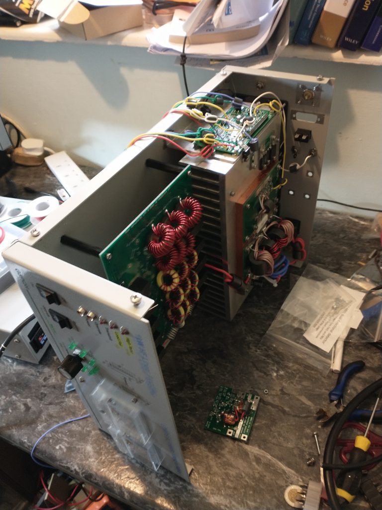
The photo above shows the amplifier under construction before most of the wiring. On the side of the heatsink the W6PQL control board can be seen with some of the control wiring.
Testing
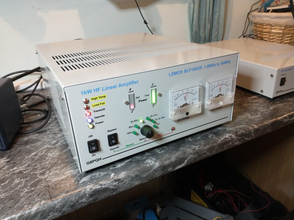
This is a view of the finished amplifier with the covers off when testing into a dummy load.
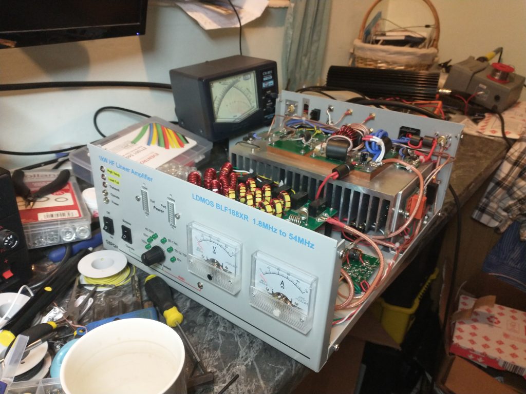
The Tx/Rx relays can be seen mounted on the right hand side of the heatsink along with the low pass filter board in front of the heatsink. The smaller board mounted on the base is one of the two directional couplers used to sense forward and reflected power.
Initially the unit was powered up with a current limited bench supply that could go up to 30V at 3A. I first checked the control board circuitry was running and 13.8V was being generated for this and the relays etc from the 50V supply. The three fans mounted on the rear panel are powered from the 50V switched by the control board.
Putting the unit into transmit with no drive on the lab supply did not release any smoke. This was then swapped out for the 50V 40A supply for further tyesting.
Ebay was the source of a hefty dummy load rated at 1000W for 3 minutes and this was used for testing and to give a rough calibration to the two led displays on the front. The amplifier was able to produce around 1000W key down into the dummy load with varying levels of drive from the Sun SDR2 DX. With the 13dB attenuator on the amp input the drive level never went over 5W (100W into the attenuator).
The directional coupler is 10 times more sensitive for reflected power so the nominal LED scale is 0-100W for reflected and 0-1000W for forward. By my calculation then when both displays give similar readings the VSWR is 2:1 (approx 10dB return loss).
In normal operation the amplifier will be run to keep the output down to 400W or less. So I adjusted the LED meter sensitivity so the top display point was roughly around 600W measured on the CN801 cross needle power meter.
Next Steps
Driving the amplifier with another hf rig, say my K2, may free up the SDR wideband 0-80MHz receiver to be used to look for harmonic levels in the output and possibly intermodulation with a two-tone test. A spectrum analyzer would be better, but I dont have one!
A few cosmetic changes are needed, you will see I have mounted the to switches upside down (oops) and there are some cosmetic bits still to be fitted near the LED bar graphs.