Amateur Satellite Communication
The first artificial satellite, “Sputnik”, was launched by the Soviet Union in 1957 into a low earth orbit (LEO) triggering the space race between the USA and USSR. Its remembered by radio enthusiasts for continually transmitting the letters “HI” in Morse Code (CW) at 20MHz and 40MHz as it circled the globe. Only four years later US radio amateurs were launching their own satellite OSCAR-1 in 1961, The OSCAR (Orbital Satellite Carrying Amateur Radio) had a similar CW beacon operating at 145MHz in the 2 metre amateur band. OSCAR-3 launched in 1965 was the first amateur satellite with a transponder enabling two way communication between amateur stations. These early efforts morphed into AMSAT (Amateur Satellite Corporation) in 1969. Over the next 50 years groups of amateur enthusiasts working through AMSAT and in partnership often with universities have developed and launched many innovative satellites. Typically in a low earth orbit these satellites can be tracked across the sky and provide communications capabilities and telemetry whilst overhead. In the UK the University of Surrey got involved in the 1980s building OSCAR 9 (aka UOSAT_1) launched in 1981 and then a wholes series of small satellites for both amateur and commercial purposes leading ultimately to the formation of the commercial spin off company Surrey Satellite Technology (SSTL).
https://en.wikipedia.org/wiki/OSCAR_1
https://en.wikipedia.org/wiki/OSCAR_3
QO-100 Satellite
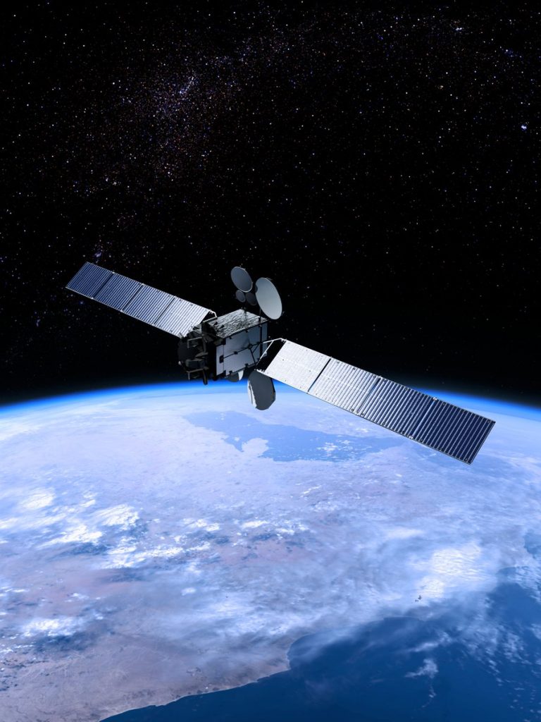
Launched in 2018, QO-100 (Qatari OSCAR 100) is the first ever geostationary amateur communications satellite. Developed by a partnership between AMSAT -DL (Germany) and the authorities in Qatar it consists of two amateur designed transponders forming a small part of the payload of the Qatari Es Hail 2 TV Broadcast satellite.
A geostationary satellite is an earth-orbiting satellite placed at an altitude of approximately 35,800 kilometres (22,300 miles) directly over the equator, that revolves in the same direction the earth rotates (west to east). At this altitude, one orbit takes 24 hours, the same length of time as the earth requires to rotate once on its axis. The term geostationary comes from the fact that such a satellite appears nearly stationary in the sky as seen by a ground-based observer. The concept was first proposed by the English writer Arthur C Clarke.
https://en.wikipedia.org/wiki/Arthur_C._Clarke
QO-100 Coverage Area
A single geostationary satellite is on a line of sight with about 40 percent of the earth’s surface. A geostationary satellite can be accessed using a directional antenna, usually a small dish, aimed at the spot in the sky where the satellite appears to hover. The principal advantage of this type of satellite is the fact that an earthbound directional antenna can be aimed and then left in position without further adjustment. The distance that a radio signal must travel to and from a geostationary satellite is a minimum of 71,600 kilometres or 44,600 miles. Thus, a delay of at least 240 milliseconds is introduced when the radio signal, traveling at 300,000 kilometres per second makes a round trip from the surface to the satellite and back.
Unlike the spot beams used for TV the QO-100 transponders have simple unidirectional antennas, the coverage area is shown below. The green line is the region where the satellite will appear 10 degrees above the horizon or more and the red line shows the region where the elevation angle is only 5 degrees above the horizon.
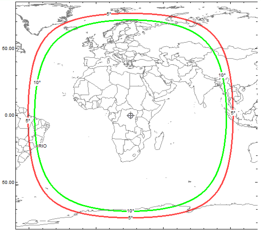
QO-100 therefore provides continuous communications over a vast area stretching from Brazil in the west through to India Cambodia and Laos in the East and from Iceland and arctic Scandinavia in the north to Antarctica in the south. The potential for reliable communication in remote areas is obvious.
Es’hail-2 / AMSAT Phase 4-A / Qatar-OSCAR 100 – AMSAT-Deutschland (amsat-dl.org)
Transponder Information
We can access two transponders on the satellite. Both the narrowband transponder and the wideband transponder have uplinks in the 2.4GHz (13cm) amateur band and downlinks in the 10GHz (3cm) amateur band. These aren’t commonly used amateur bands, there is little or no commercially built equipment. However the uplink band is immediately adjacent to the main WiFi band and the downlink band is adjacent to a band commonly used for satellite tv, this presents numerous opportunities for adapting or repurposing equipment designed for these other services.
Narrowband Transponder Bandplan
The narrowband linear transponder receives signals transmitted between 2400MHz and 2400.5MHz and re-transmits what it receives from 10489.5MHz to 10490.0MHz.
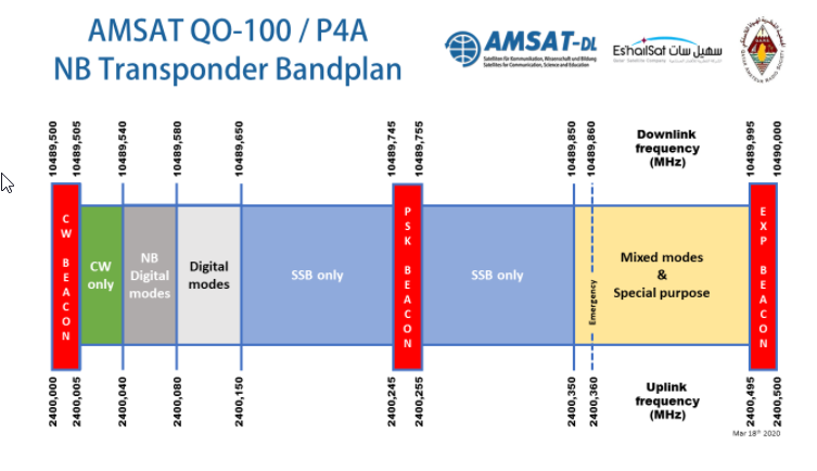
Spectrum reserved for beacons is shown in red. At the lower end of the band is a CW beacon, at the upper end a simple FSK beacon and in the centre of the passband an FSK telemetry beacon using the AMSAT format first used on the AO40 satellite.
The 500kHz band is utilised in a similar way to most other amateur bands with frequencies at the lower end reserved for CW and data modes and the middle and higher parts of the spectrum used for SSB voice. AMSAT have decided that the max spectrum used for any one signal should be the typical SSB bandwidth of 2.7KHz. This rules out using conventional AM or FM speech modes. I haven’t seen much CW activity, but SSTV using the KG-SSTV mode is commonly seen, digital voice and some FT8 data modes. Its easy to monitor activity on the narrowband transponder using the web sdr at the Goonhilly ground station in Cornwall. QO-100 / Es’hail-2 Narrowband WebSDR (batc.org.uk)
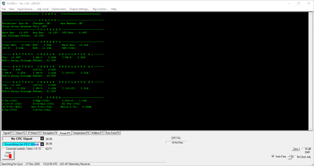
Telemetry decoded gives information on the current operational staus of the various systems on board the satellite.
The 10GHz downlink signals are vertically polarised. The uplink signals should ideally have Right Hand Circular Polarisation (RHCP). Using linear polarisation will incur a 3dB loss.
The transponder link budgets and practical performance are such that a common “sky dish” 60 to 80cm offset feed satellite tv dish and standard satellite tv PLL type LNB will provide good receive results. There is no advantage in using dishes bigger than 1.2m on receive as you will not increase the signal to noise ratio which is limited by the transponder to a max of about 18dB in a 2.7kHz bandwidth. The uplink transmitter can use the same dish with a feed based on a small helix or patch antenna at 2.4GHz. The gain at the lower frequency is less (around 22dBi) meaning around 5W transmitter power is needed on the uplink for SSB voice communication. Less for data modes.
Wideband Transponder Bandplan
The wideband transponder is a linear transponder with an 8MHz bandwidth. The uplink starts at 2401.5MHz and runs to 2409.5MHz with the corresponding downlink at 10491.0MHz to 10499.0MHz. It has mainly been used for digital amateur tv transmissions using the DVB-S2 standard with a range of symbol rates. However other uses are possible including exprimental Lora chirp spread spectrum data with a 125kHz bandwidth.
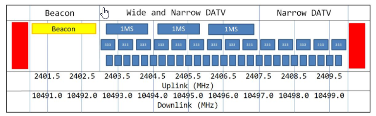
There are upper and lower telemetry beacon transmissions shown in red and a 1.5Mega-symbol per second DVB-S2 tv transmission, also described as a beacon, that gives information about QO-100 (shown in yellow) that is useful for testing tv reception. Above this there are defined centre channels for 1Msymbol/s digital tv signals as well as narrower bandwidth transmissions using 333ksymbol/s and 125ksymbol/s.
The British Amateur Television Club web SDR is very useful for monitoring activity and allows users to chat to each other and detail the formats of their transmissions, QO-100 / Es’hail-2 Wideband Spectrum Monitor (batc.org.uk)
The downlink signals on the wideband transponder are vertically polarised. the uplink uses RHCP same as the narrowband transceiver. A better link budget is needed to support wider bandwidth transmission.
At least a 1.2m dish is needed to support TV. A 30W power amplifier can support narrowband tv at up to 250kSymbols/s but higher power is needed for HDTV operation. Around 120W will be needed for 1Msymbols/s video.