HF Propagation Prediction
Transmitting TV via QO100
On 23rd April 2023 I made my first two-way amateur television contact with stations in South Africa, Brazil and elsewhere in the UK joining the Sunday DATV net run by Gary ZS6YI.
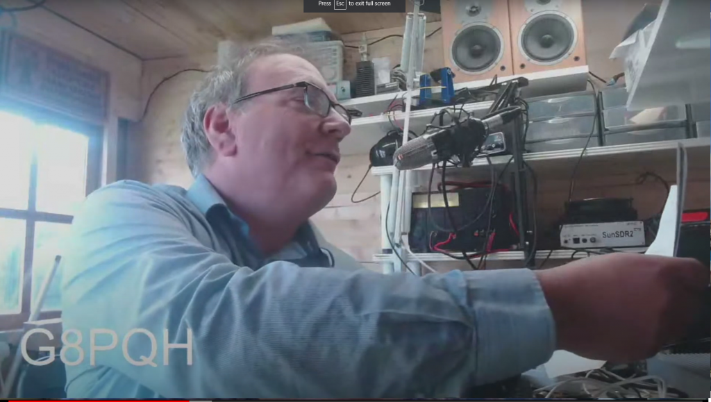
Off air pictures 23/4/23
Since moving to the new QTH in Selsey, I have been experimenting with Digital Amateur Television (DATV) using the geostationary QO100 satellite. During 2022 I was able to transmit some jerky pictures at a fairly low frame rate and resolution through the satellite and receive them. By April 2023 I was experimenting with more power on the uplink and was able to make two way contacts.
(I had an interest in television transmission back in the 1980s when a group of us managed to get on the air on 70cm from out student digs in London, although the technology of the time was very different! My Radio History)
During the summer I have gradually improved my ability to send and receive pictures, though I haven’t got it perfect quite yet.
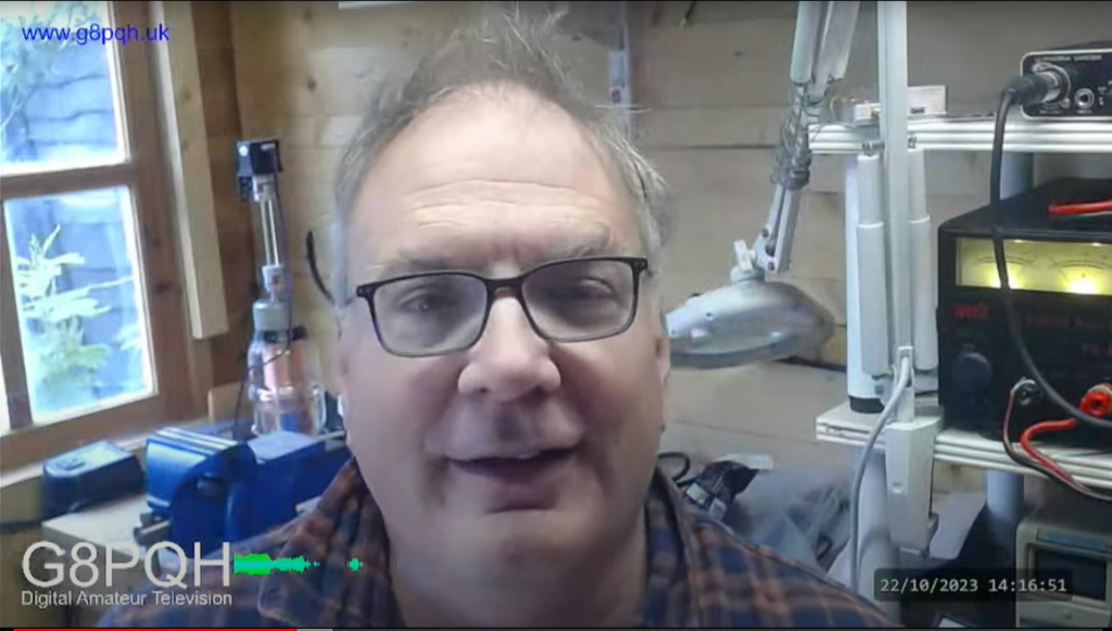
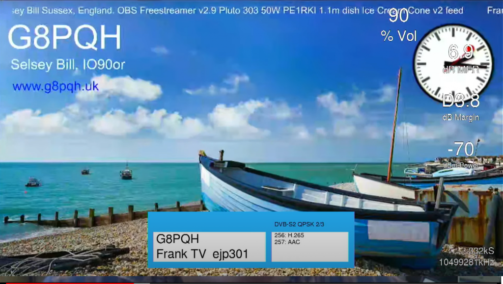
720p resolution pictures received by Gary ZS6YI in South Africa 22/10/23 DVB S2 333kSymbols FEC 2/3
Gary has an excellent receive setup and is receiving my signals with a margin of around 3.8dB. The image below from the beginning of my transmission shows his receiver details superimposed on the right hand side and the programme details in the central box. (These disappear after a few seconds).
I have added some information on my DATV set up on this page. DATV on QO100
I think I have learnt a lot already and hopefully I will be able to continue to improve my station and make many more contacts.
1kW Linear Amplifier Part 3: Build Up and Testing
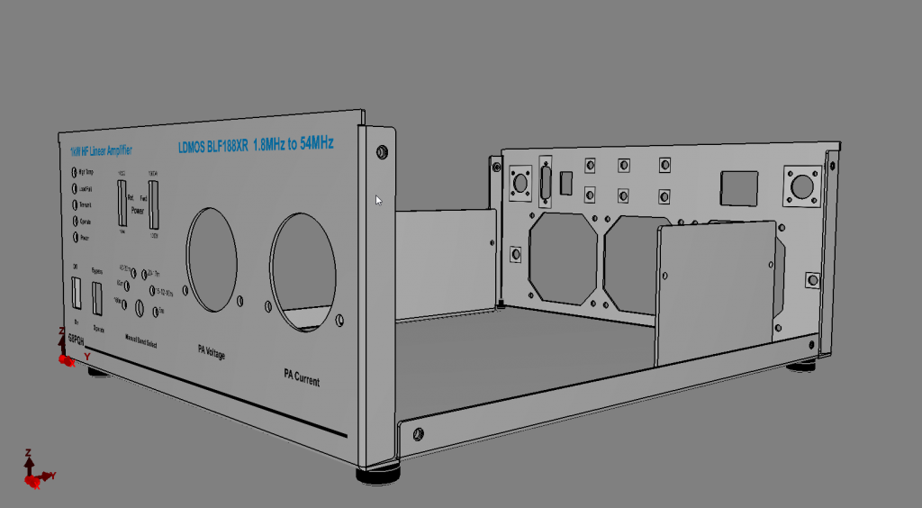
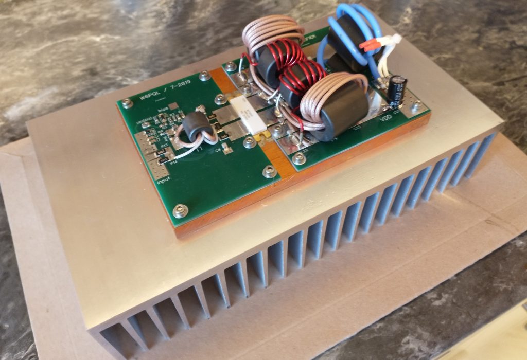
The general mechanical layout of the amplifier follows the W6PQL layout fairly closely.
The main difference is that the recommended heatsink he suggests is a bit expensive when you factor in shipping charges to the UK plus VAT & Customs etc. So I sourced a relatively inexpensive heatsink from the supplier TME in Poland which I think will have similar performance but is slightly longer, so makes the cabinet wider. This makes the whole box for the amplifier wider. For this reason I have the two meters for PA voltage and current side by side rather than one on top of each other as W6PQL does.
Mechanical Details
My metal working facilities are very limited, and my skill at it even more so. So rather than have separate panels bolted together I had a sheet metal box fabricated by an online vendor. A bit of a vanity project, as it looks nice and saves a lot of metal bashing, but is a cost. Another alternative could have been to mount the LPF alongside the heatsink and use a 19″ cabinet. That would be wider, but a lot shallower.`
Three fans are mounted on the rear panel along with RF connectors, power, PTT . SMA RF connectors are used to bring out connections to a 13dB 100W attenuator that can be placed in circuit when 100W transceivers are used to drive the amplifier, or bypassed when 5W radios are used to drive the amplifier. The heatsink is mounted at the rear lengthwise with the amplifier pallet and its copper heat spreader bolted to that.
The low pass filter assembly is mounted in front of the heatsink together with directional couplers for forward & reflected power display (after the filter) and amplifier load fail or wrong band lockout (before the filter). The front panel has metering, status LEDs, a band change switch with indicator LEDs and bar graphs for forward and reflected power.
The photo above shows the amplifier under construction before most of the wiring. On the side of the heatsink the W6PQL control board can be seen with some of the control wiring.
Testing
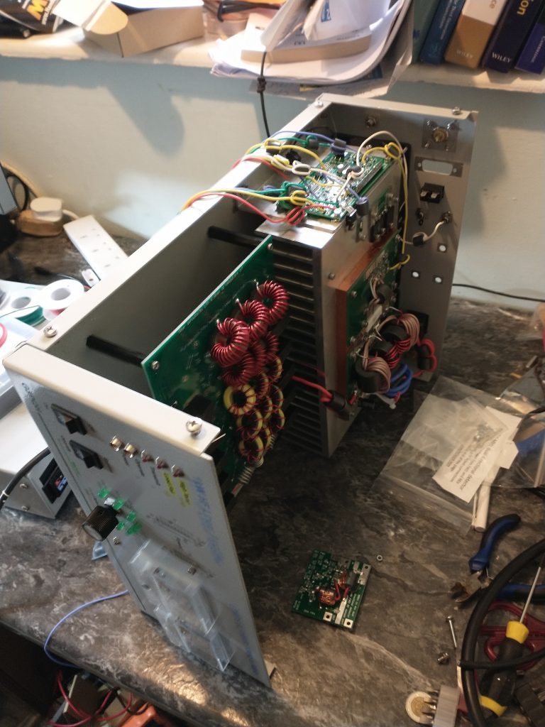
This is a view of the finished amplifier with the covers off when testing into a dummy load.
The Tx/Rx relays can be seen mounted on the right hand side of the heatsink along with the low pass filter board in front of the heatsink. The smaller board mounted on the base is one of the two directional couplers used to sense forward and reflected power.
Initially the unit was powered up with a current limited bench supply that could go up to 30V at 3A. I first checked the control board circuitry was running and 13.8V was being generated for this and the relays etc from the 50V supply. The three fans mounted on the rear panel are powered from the 50V switched by the control board.
Putting the unit into transmit with no drive on the lab supply did not release any smoke. This was then swapped out for the 50V 40A supply for further tyesting.
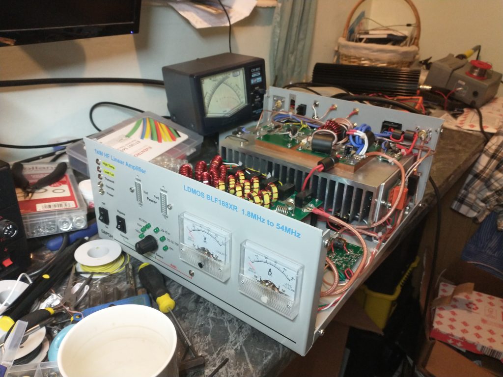
Ebay was the source of a hefty dummy load rated at 1000W for 3 minutes and this was used for testing and to give a rough calibration to the two led displays on the front. The amplifier was able to produce around 1000W key down into the dummy load with varying levels of drive from the Sun SDR2 DX. With the 13dB attenuator on the amp input the drive level never went over 5W (100W into the attenuator).
The directional coupler is 10 times more sensitive for reflected power so the nominal LED scale is 0-100W for reflected and 0-1000W for forward. By my calculation then when both displays give similar readings the VSWR is 2:1 (approx 10dB return loss).
In normal operation the amplifier will be run to keep the output down to 400W or less. So I adjusted the LED meter sensitivity so the top display point was roughly around 600W measured on the CN801 cross needle power meter.
Next Steps
Driving the amplifier with another hf rig, say my K2, may free up the SDR wideband 0-80MHz receiver to be used to look for harmonic levels in the output and possibly intermodulation with a two-tone test. A spectrum analyzer would be better, but I dont have one!
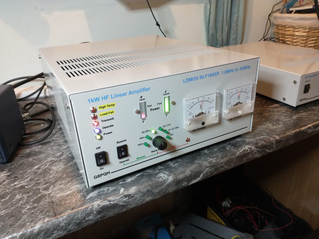
A few cosmetic changes are needed, you will see I have mounted the to switches upside down (oops) and there are some cosmetic bits still to be fitted near the LED bar graphs.
1kW LDMOS Linear Amplifier – Part 2 Low Pass Filter
Based on designs by James, W6PQL
And in particular his HF LDMOS amplifier design described here:
https://www.w6pql.com/1_kw_sspa_for_1_8-54_mhz.htm
A key part of the amplifier is the switchable low pass filter design. This is designed to suppress the odd-order harmonics in the amplifier output which would be unacceptably high without it.
Construction
I built up the filter assembly from the the pcb and components supplied by W6PQL I tested it using the well known nanoVNA and the results are set out here.
A full description of James’s design can be found here: https://www.w6pql.com/a_1.5kw_lpf_for_160-6m.htm
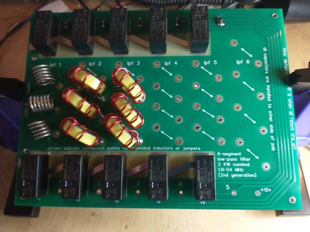
The board supports 6 different filters. With no relays energised the sixth filter for the 150m band (1.8-2MHz) is in circuit. Each of the five pairs of relays switch an alternative filter bank when energised by grounding the control inputs. The following filters are equipped:
- 160m band (default) <2MHz
- 80m band (#5) <4MHz
- 40m and 30m <10.2 MHz
- 20m and 17m bands <18.2MHz
- 15m, 12m and 10m bands < 30MHz
- 6m band <54MHz
Each of the low pass filter filter sections are 7-pole Chebyshev types which should give sufficient harmonic rejection.
The top side of the board has the relays and the toroidal coils, all except the 6m band use ferrites of different types. The bottom side has a great number of surface mount capacitors, which are easy to mount with some tweezers and patience, soldering one side at a time. (I managed to wick some solder between two adjacent capacitors to produce a hard to spot short in the 160m section which uses a lot of capacitors in parallel) But this was more or less the first time I had done much with SMD and easy to fix once spotted.
Testing
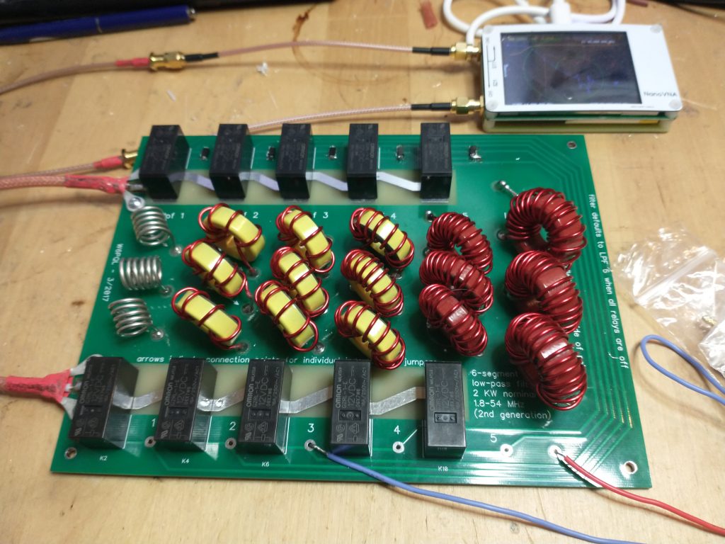
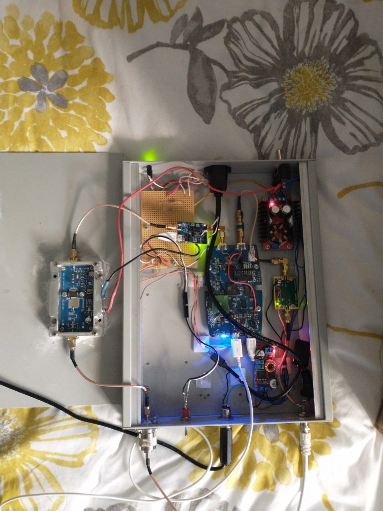
To test the assembly I made use of an inexpensive nanoVNA unit, bought from eBay. The VNA is the white box in the top right connected to a PC via a USB cable. The two SMA connectors on the VNA are cabled to the the input and output of the the filter unit. The red wire at the bottom right is feeding 12V from a bench PSU to the board. with no ground applied to the control inputs the 160m filter is in circuit. By grounding each of the five control inputs in turn with the blue wire each of the filters in turn is placed in circuit and the performance measured by the nanoVNA.
James, W6PQL has a collection of S21 gain/loss plots and S11 return loss plots on his web site. Being an ex HP engineer, I suspect he has access to a conventional high performance network analyser for his testing. However, I figured the nanoVNA would at least confirm the correct operation of the unit I assembled and highlight any errors in construction. In practice my results were very close to the example plots on the W6PQL website.
I have found it is much easier to use Ruhne Broberg’s open source software nanoVNASaver on the connected PC. Life is too short to spend too much time faffing about with the fiddly buttons and soft keys on the nanoVNA unit itself.
https://github.com/mihtjel/nanovna-saver/releases
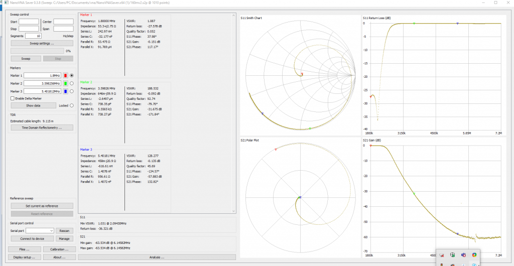
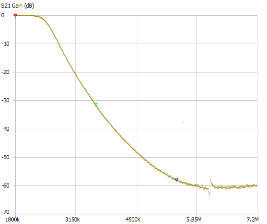
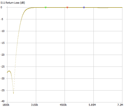
Results – 160m band
Second harmonic suppression at 3.6MHz was around -32dB and third harmonic suppression at 5.4MHz was -58dB. The in-band return loss was always better than 25dB. The filtered harmonic content will be reflected directly back to the source as the return loss at these frequencies is zero.
Results – 80m band
Second harmonic suppression at 7MHz was around -30dB and third harmonic suppression at 10.5MHz was -53dB.
Results – 40m and 30m bands
Second harmonic suppression of the 7MHz (40m band) signal at 14MHz was around -20dB and third harmonic suppression at 21MHz was -48dB.
Results – 20m and 17m bands
Second harmonic suppression of the 14MHz (20m band) signal at 28MHz was around -27dB and third harmonic suppression at 42MHz was -49dB.
Results – 15m, 12m and 10m bands
Second harmonic suppression of the 21MHz (15m band) signal at 42MHz was around -17dB and third harmonic suppression at 63MHz was -45dB.
Results – 6m band
Second harmonic suppression of the 50MHz (6m band) signal at 100MHz was around -29dB and third harmonic suppression at 150MHz was -60dB.
Performance Implications
At 1000w key down the even order harmonics in the push-pull LDMOS design are reasonable but the odd-order harmonics are truly monstrous. W6PQL reports the third order harmonic as only 10dB down on the fundamental.
The minimum suppression of third order products in these filters is around 45 dB for the compromise filter covering three bands, 15m, 17m, and 10m. So at full power we might see a third order product at aroound-55dB below the carrier (-55dBc).
This is not too bad. In the USA amateurs must achieve -43dBc in part 97 of the FCC regulations. In the UK/EU its -50dBc for commercially built equipment intended for HF Amateur Radio use (-60dBc for other services). For UK amateurs building their own equipment the licence conditions are very “British” in their avoidance of prescription saying merely “the emitted frequency of the apparatus comprised in the Radio Equipment is as stable and as free from Unwanted Emissions as the state of technical development for amateur radio apparatus reasonably permits.”
I think hitting -50dBc in looks to be more than “reasonable” to me and should be possible.
Another important point is that UK amateurs are only allowed to run at 400W (26dBW) in most bands which is 4dB less than what the amplifier to be filtered is capable of. The designer doesn’t give any harmonic output figures when the amplifier is not driven so hard. However I would expect the 3rd harmonic to fall three times as fast as the fundamental, so be reduced by a further 12dB when run at the UK limit. This would indicate a worst case 3rd harmonic output at least -67dBc under these more benign conditions.
Running at 400W should also improve the in-band intermodulation performance of the amplifier.
Space Communications: First contact thru QO-100
Over Christmas 2020 I’ve made my first contact via the narrowband amateur transponder on Es’Hail QO-100 geostationary satellite. Its not as tricky as you might think!
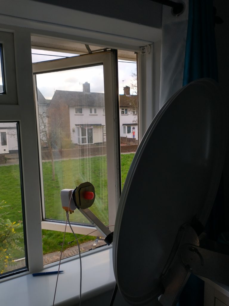
My portable setup being tested indoors in the warm, (not ideal). (More details on SatCom pages). Whilst counting and repeating nursery rhymes to myself, I was called by Prem VU2OLU in Kerala southern India. Not bad for a first contact.
I made this recording of our QSO. (Its from the webSDR at Goonhilly earth station)
QO-100 / Es’hail-2 Narrowband WebSDR (batc.org.uk)
Transceiver setup is based on the Adalm Pluto SDR and SG Labs PA shown here with the box lid off sitting next to the dish on the bed.
1kW LDMOS Linear Amplifier – Part 1 (PSU)
Based on designs by W6PQL
First step in building such an amplifier as described here:
https://www.w6pql.com/1_kw_sspa_for_1_8-54_mhz.htm
is rigging up a power supply capable of delivering 50Volt at more than 35Amp.
There are a number of ways of doing this, telecoms power supply units (48V) can often be found on ebay, but like server power units can be very noisy. Its also possible to put together sets of 12 and 24 V switched mode PSUs with steering diodes etc to build a powerful combined unit. W6PQL describes such an approach on his web site.
I was lucky in that I managed to find a surplus Meanwell 48V 2400W power supply unit going cheap. Therefore my PSU is basically one of these units, encased in a slightly larger box with the addition of some switches and an ammeter to measure the current. Simple.
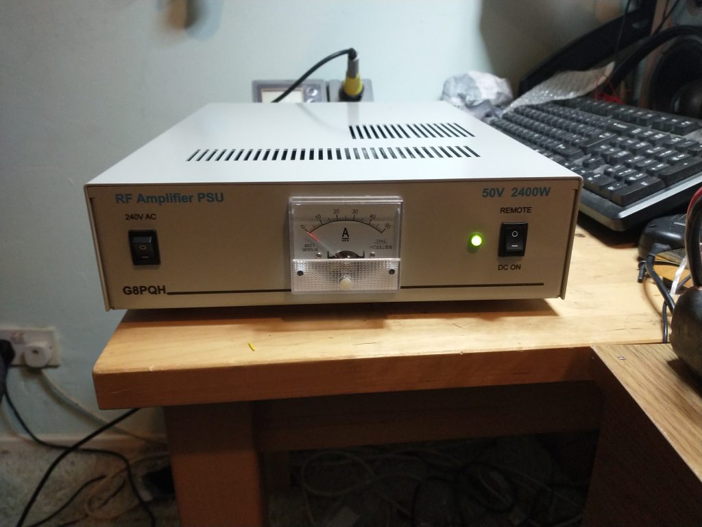
The connections are at the rear.
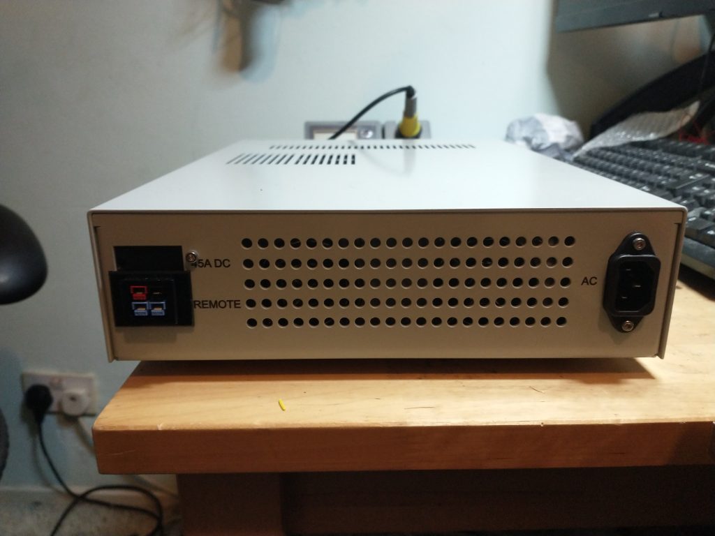
Inside its very simple.
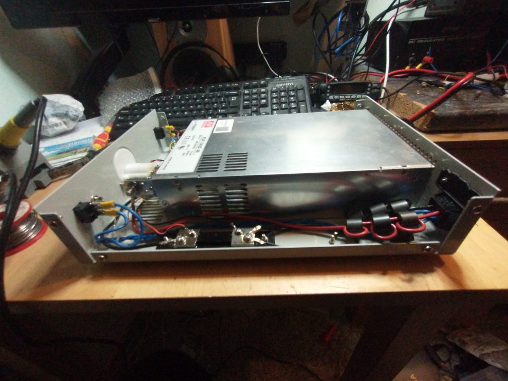
In this image you can see the Anderson PowerPole connectors for the DC output on the rear and the cabling to them with ferrite beads aimed at reducing the RF on the wiring. Theres also a 75mV shunt on the negative output which is used to drive the ammeter on the front panel.
The pSU can be remotely turned on and off by shorting the remote input (two blue powerpole connectors) together from the attached LDMOS amplifier, or by setting the front panel switch to local.
End Fed Half Wave Antenna
As an alternative to the inverted L, ground system and auto-tuner I have been experimenting with the end fed half wave antenna (EFHW), sometimes known as the “Little Dutch Girl”. Feeding a half wave length of wire at the far end rather than in the middle as per the classic dipole means that the impedance at the feed point will be high. Around the order of 2500 ohms at resonance.
A 1:49 matching transformer is used to match the output of the transmitter and feedline to the antenna. These are conventionally made by winding transformers on a ferrite core with a 1:7 turns ratio.
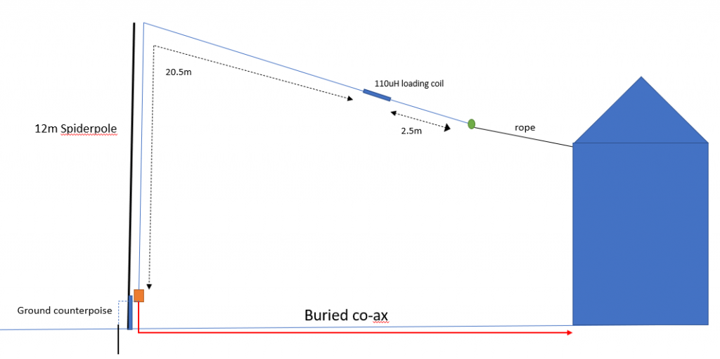
In my small garden even with an inverted configuration as shown the lowest frequency I can fit half a wavelength in is 7MHz for the 40 meter amateur band. I have used an additional 2 meters of length to add a loading coil and a 1.5m length of wire to add a capability at 3.65MHz in the 80m amateur band.
I experimented with a commercial transformer, but ended up replacing most of the parts with more heavy duty components.
Here’s my 1:49 transformer based around 2 X FT240-43 ferrite cores:
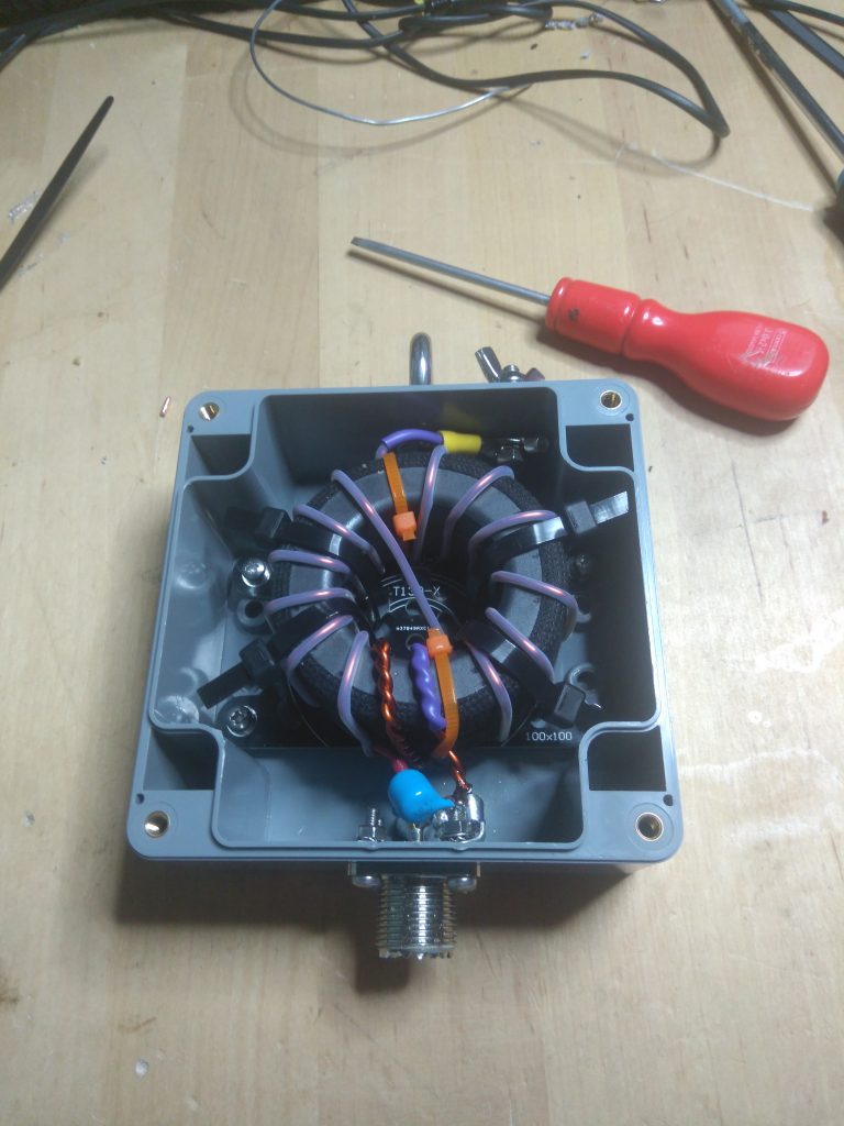
In theory should be good for around 400W RMS or 1kW PEP.
And here’s the unit mounted at the bottom of the garden.
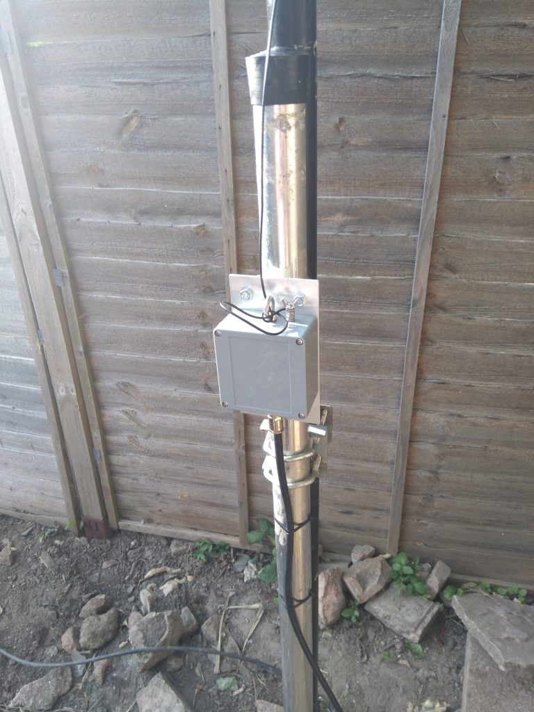
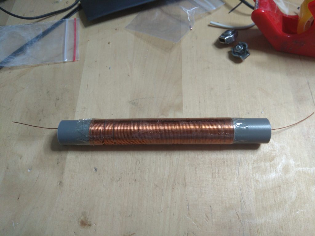
and the loading coil mounted on a former for the 80m band.
SDR HF/VHF Transceiver
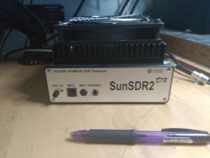
I recently got hold of SunSDR2 DX 100W +HF/VHF SDR transceiver
What it is
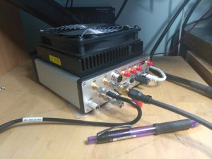
It does a hell of a lot for its very small size. Unlike the photos on Expert electronic’s website it comes with a 140mm fan fitted to the top of the heatsink. The entire unit is not much bigger than the dimensions of the fan as you can see in these photos.
 |
 |
The fan is completely silent in use and appears thermostatically controlled with varying speeds. On the back panel the unit I received is fitted with a useful looking ground binding post.
An ethernet cable connects to your PC. You have to run the software the manufacturer provides, but it has a lot of features, some of which I am still discovering.
This unit is a higher power version of the the better known SunSDR2 Pro which has been available for a few years. Apart from the power difference, there is apparently better filters and an improved power supply. It certainly doesn’t run hot in use, like people have noted the older unit did. Possibly this is down to the large, but whisper quiet fan mounted on the top.
Technology
The receive signals end up heading into to an ADC (LTC2209) that takes full, 16-bit, samples at a rate of 160Msps (Mega samples per second). These samples contain way too much data to pass straight to a PC so the SunSDR2 DX employs an Altera Cyclone IV FPGA (Field Programmable Gate Array) to decimate the ADC output and deliver chunks of spectrum at a more manageable data rate that can be passed to the PC software for final processing. Two independent decimation feeds are available which means that the software can operate with two entirely independent receivers for split operation anywhere in the tuning range. Management of the band switching, FPGA decimation, SWR bridge and other functions is handled by an LPC1778 Cortex M3 based microcontroller. This controller also links to the on-board 24-bit audio codec that handles the hardware microphone inputs and the phones output. For the transmit section, the IQ transmit signal is generated in the FPGA and passed to an Analog Devices AD9957 1Gsps, 14-bit digital to analogue converter (DAC). In this case, the DAC runs with a 640MHz clock thus allowing 640Msps for a high quality transmit signal.
Features
The system is a Russian design and the hardware itself is manufactured in Taiwan. Some of the features are set out here:
- Independent RX path based on DDC (Direct Down-Conversion) architecture
- Independent TX path based on DUC (Direct Up-Conversion) architecture
- Output power: 100W on HF, 50W on 6M and 8W on 2M ·
- 2 software RXs + SubRX for each of them (4 slices total) + independent wideband Bandscope up to 80 MHz
- Remote control operation
- TCI interface for connection with third-party software
- TX processing module provides advanced tuning capability for voice operation
- ExtCTRL connector to control external devices with 8 powerful keys with open collector
- ALC connector for external power amplifiers
- Supports use of VHF transverters (coming soon)
- An opportunity to use the transceiver as a signal generator via DAC OUT connector (SMA connector) ·
- An opportunity to use external filters in the middle of the RF path, using ADC IN and RX OUT (SMA connector) ·
- A small delay in CW mode (about 10 ms)
- Input for external 10 MHz reference oscillator ·
- An opportunity to use the transceiver in SO2V mode ·
- Full duplex or half duplex modes (in future) ·
- Antenna switch with 2 HF antenna connectors and separate VHF antenna connector (Mini UHF connectors) ·
- Internal power-meter for HF and VHF bands and SWR-meter for HF band ·
- Ethernet LAN interface to PC
Operational Experience
I’m using it with a small fanless PC, an i7 8565 @1.8GHz with 16GByte RAM and Windows 10. The Expert SDR Software could also run under Linux.(Ubuntu). Setting up was not that complicated, basically setting the right IP addresses for the PC LAN port and connecting a short ethernet cable between the PC and the transceiver. The addendum to the manual is very useful as it goes through how to set up virtual audio cables and virtual com ports to connect to other software packages. I’m using WSJT-X & FLDIGI for datamodes and also Swisslog for logging. FT8 operation is particularly easy with rx and tx audio and CAT control being handled by virtual audio and serial ports. Swisslog also automatically logs FT8 contacts and tracks you band etc
The transceiver will support a Yauseu MH43 mic with an RJ45 connector plugged straight in. In my case however I have the audio coming from the PC. I have an AKG mic feeding an external USB soundcard that also powers the mic (Behringer UMC22) and this seems to work very well. Hours of fun can be had (if you like the sound of your own voice) playing around with the audio on transmit. The unit offers a very large array of equalisation/compression/clipping/bandwidth options and you can save your settings to different named profiles so that different audio characteristics can be selected for say SSB weak-signal, local ragchew, FM operation on 2 or 6m etc etc.
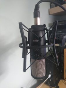
The AKG mic on its boom, in the background the fanless PC can be seen. There are a lot of audio adjustments, but you can monitor your own transmission easily and also record something and re-transmit it and monitor on Hack Green. I noted a recent QSO on 60m AM on 5317kHz was recorded by John, G3YPZ on the Facebook AM Amateur Radio Europe and he seemed to find the transmitted audio fine, so I’m happy.
I’ve linked to John’s facebook post below where you can hear me waffling away in one of the early contacts I had with the Sun SDR2 DX, which was doubly unusual being both on 60m and using good old AM. These are a band and modes which of course I can’t access on either of the other two HF rigs here, my Elecraft K2, or the TS520S, both being too modern for AM (SSB only) but not modern enough for the 60m band!
Posted by John Petters on Sunday, 5 April 2020
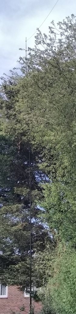
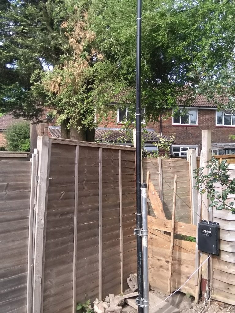
Inverted L up and running
Spiderbeam 12m pole is up at the bottom of garden with Inverted L antenna, sloping back down to the house. Some encouraging results so far on 40m and 80m with US,European and North African contacts on 40m and daytime 80m signals being received at the Hack Green SDR. Clearly hiding the antenna in a tree hasn’t made much of a difference
Irritatingly I have managed to disable my K2 transceiver on Tx by shorting the VRFDetect line to 12V on the AuxIO sokcet when making up a RS232c lead for rig control and being a bit clumsy with a scope probe. Oh Well. I have had to send off to Elecraft for a new programmed MCU chip, as the A/D input is damaged and its taking an age to come!
 |
 |
Backyard HF Antenna project
I have been planning a return to HF operation, so the question of stealthy (small) backyard antennas comes up. The available space is the typical ‘not much’, roughly 55ft by 30ft
Plan A is an inverted L, fed via an auto ATU at the far end of the garden, with the horizontal section of the “L” coming back towards the house. So far A CG3000 auto-tuner has been obtained on ebay, and a 12m “Spiderbeam” telescopic fibreglass pole. Every plan should have a sketch, so here’s mine:
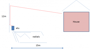
So the ATU will not tune easily a length of wire close to 1/2 a wavelength or multiples pf half a wavelength. I reckon the wire length will be around 23m. I have to keep away from 21m which is a half wavelength at 7.1MHz and multiples at 14.2 and 21.3MHz (!)
I plan to run radials under the lawn and along the bottom part of the wooden fencing.