Quite a few Amateur Radio operators are interested in operating at the highest transmit power they can within the term of their licence. But higher power brings problems and expense and is not always justified.
Valve (Tube) vs Transistor
In the UK operation is limited to a peak envelope power (PEP) of 400W on most bands. In other countries more is permitted, for example 1500W PEP in the USA. Typical HF transceivers for example have a power level of around 100W, so additional amplifiers can be found in use to boost the power up by a useful 6dB to 400W or 11/12dB or so to around 1500W in other countries.
Most of these amplifiers have used valves (tubes) rather than transistors. Valve amplifiers have a number of advantages. They can be relatively simple and inexpensive. They can deliver power into antenna systems with a poor VSWR or return loss. As long as they are not overdriven they can deliver good intermodulation (IMD) performance and the output circuitry suppresses higher order harmonics.
However they have always had a number of disadvantages. The output circuits are not broadband and you have to tune/retune them every time you change band or frequency. They usually take a few minutes to warm up when you want to use them. The Anode (Plate) voltages can be thousands of volts meaning that the power supply circuits are potentially lethal. The valves wear out and need to be replaced after some years of operation. Finally the valves themselves are in short supply and modern Chinese copies of the original designs from way back when are not as good.
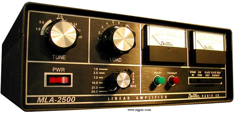
The Amp I used in the club station when I was a student was the Dentron MLA2500. Probably not the greatest piece of equipment but I always fancied one. Nowadays the valves it used (8875) are unobtainable and it has to be converted to use Russian tubes. Perhaps not the best second-hand by on ebay then after all.
Transistor amplifiers have struggled to match valve amplifiers on IMD performance, they usually need antennas tuners to operate into antennas with a VSWR > 1.5 and they need high performance low pass filters for each band to bring harmonics in the output down to acceptable levels. They can be fragile and unforgiving of mistakes. They need complex monitoring and protection circuits to ensure device survival in the face of antenna faults and operator error. Commercial units can be very expensive.
On the plus side they don’t operate at lethal voltages, current devices are much less fragile, they don’t need tuning and retuning on frequency change and they are on instantly with no need to warm-up. You also wont be so reliant on obsolete or hard to find parts.
They can be small, and that’s attractive for me at the moment as I don’t have a lot of space.
Buy vs Build
There are some very nice commercially built amplifiers based on LDMOS transistors available. They have a host of features, but come at a hefty price.
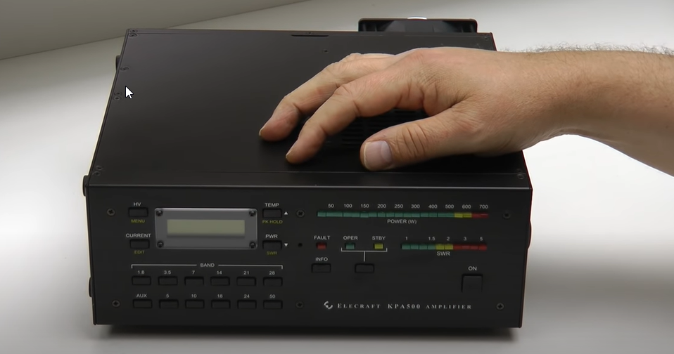
Elecrafts 1500W unit uses two pairs of LDMOS transistors BLF188XR.
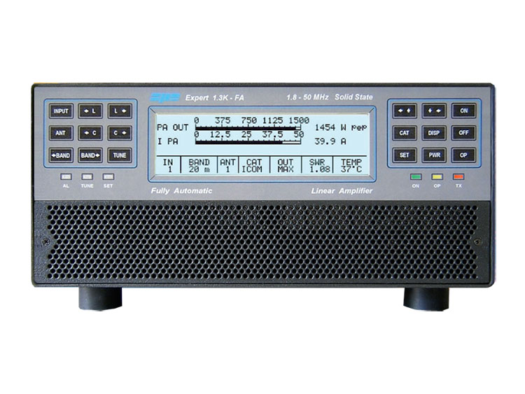
Similarly the Linear Amp UK Gemini unit also uses the same transistor. The Crawley Amateur Radio Club station includes an example of this SPE Expert 1.3K Amplifier. I have used this amplifier at the club station and its very nice indeed.
LDMOS HF Amplifier Technology
Transistor amplifiers have had a reputation for being rather fragile in Amateur Service. But LDMOS technology is a lot tougher.
The Ampleon “XR” devices (like the BLF188XR) are claimed to be extremely rugged. Here’s a “Don’t try this at home video”.
Not that you have that much test equipment at home 🙂
A Crazy Idea, but it might just work!
Why not build one’s own LDMOS amplifier as a lock down project. Well lets cheat a little and not start from scratch. James W6PQL a retired HP engineer living in California has designed a number of key modules that can be put together to build such a unit. So this was the route I tried.